 CZ
CZ
Direct Ignition TCI
Již není v prodeji!
Náhradou je zapalování MASTER MINI.
Zapalování Direct Ignition je zapalování s řízením předstihu zážehu pro spalovací motory sportovních a hobby strojů. Řízení předstihu je možné dle dvou nastavitelných křivek v rozsahu 0 až 90° při otáčkách 180 až 20.500 ot/min. Zapalování umožňuje spínání buzení jedné a nebo zcela nezávislé buzení dvou indukčních cívek. Veškeré funkce a volitelné pracovní režimy zapalování je možné nastavit pomocí osobního počítače. K tomuto účelu slouží aplikace Ignition Control, která současně umožňuje Online vizualizaci skutečných hodnot otáček, předstihu, analogových a digitálních vstupů. K propojení osobního počítače a zapalování slouží propojovací USB kabel.


Technická specifikace
Analogové a digitální vstupy a výstupy umožňují realizaci rozšířených funkcí, např.: přepínání křivek předstihu, blokování buzení, výstup otáčkoměru, spínání signalizace řadících otáček, připojení teplotního, podtlakového čidla s možností zadání korekcí předstihu zážehu.
Řízení předstihu zážehu je realizováno přepočtem žádané křivky předstihu zážehu na tabulku časových zpoždění. V závislosti na aktuálních otáčkách motoru jsou jednotlivá časová zpoždění z tabulky vybírána a prostřednictvím mikroprocesoru přesně odměřována, čímž dochází k výslednému efektu řízení předstihu.
Aplikace Ignition Control nově poskytuje funkci pro ladění předstihu pomocí akcelerační brzdy, kde se sleduje zrychlení motoru při překonávání vlastní hmoty. Předpokladem je, že zrychlení otáček motoru úměrně odpovídá kroutícímu momentu motoru.
Hlavní rysy
- Indukční zapalování typu - TCI
- Rozsah napájecího napětí 3,5 až 25V
- Pracovní otáčky 0 až 25.000ot/min
- Pracovní teplota -40 až 85°C
- Použití konektorů - Tyco automotive
- Stupeň krytí IP65
- Komunikace přes USB
- Dvě volitelné křivky předstihu
- Volitelná křivka buzení indukčních cívek
- Rozšířené funkce DI1, DI2, AI1, AI2, DO1, DO2
- Změna křivek i za běhu motoru
- Sledování aktuálního stavu motoru
- Záznam doby běhu motoru
- Akcelerační brzda
Základní technické parametry zapalování
| Parametr | Rozsah |
| Napájecí napětí | 3,5 až 25V (přepěť. ochrana 33V) |
| Pracovní otáčky | 0 až 25.000 ot/min |
| Rozsah řízení předstihu | 0 až 90° |
| Otáčkový rozsah s řízením předstihu | 180 až 20.500 ot/min |
| Pracovní teplota | -40 až 85°C |
| Řízení energie jiskry | Tabulkou, Max., Med., Min., Řízená |
| Spínání buzení indukčních cívek | max. 15A / 0.085 ohm (MOSFET) |
| Odpor indukčních cívek | > 2,5 Ω (12V); > 1,5 Ω (6V) (měřeno mezi vývody 1 a 15) |
| Měření napětí sítě (palubní napětí) | 3,5 až 25V (tol. +-2%) |
| Analogové vstupy (AI1, AI2) | 0 až 2,5V; 0 až 5V; 0,2 až 2,5k ; > 2,5k |
| Analogové/digitální vstupy (AI3/DI3, AI4/DI4) | 0 až 5V / 0 až 2V = L; 3 až 20V = H |
| Digitální vstupy (DI1, DI2) | 0 až 1V = L, 3 až 20V = H |
| Digitální výstupy (DO1, DO2) | Otevřený kolektor (max. 1A, Pull up 1k) |
| Automatické odpojení buzení indukčních cívek | Odpojení za 5 až 120s po stopu motoru |
| Signalizace stavu kontrolkou | Zelená, Červená |
| Komunikace s PC přes sběrnici USB | ano |
| Stupeň krytí | IP65 |
| Vnější rozměry | 92x62x25 mm |
| Hmotnost | 250g |
Zapojení konektorů zapalování
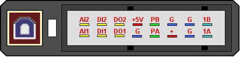
Význam vodičů konektoru
| Označení | Význam | Rozsah, aktivní úroveň |
| + | Napájení | 3,5 až 25V, (ochrana 33V) |
| G | Zemnění napájení, snímače | 0V |
| 1A | Spínání indukční cívky A | Max. 15A / 0.085Ω (MOSFET) |
| 1B | Spínání indukční cívky B | < 15A |
| +5V | Výstup pro napájení snímačů +5V | +5V, 100mA |
| PA | Snímač otáčení A | -60 až 60V, vzestupná hrana 0 -> 1,2V |
| PB | Snímač otáčení B | -60 až 60V, vzestupná hrana 0 -> 1,2V |
| AI1 | Analogový vstup 1 | 0 až 2,5V; 0 až 5V; 0,2 až 2,5kΩ; > 2,5kΩ |
| AI2 | Analogový vstup 2 | 0 až 2,5V; 0 až 5V; 0,2 až 2,5kΩ; > 2,5kΩ |
| DI1 | Digitální vstup 1 | 0 až 1V = L, 3 až 20V = H |
| DI2 | Digitální vstup 2 | 0 až 1V = L, 3 až 20V = H |
| DO1 | Digitální výstup 1 | otevřený kolektor (max. 1A, Pull up 1kΩ) |
| DO2 | Digitální výstup 2 | otevřený kolektor (max. 1A, Pull up 1kΩ) |
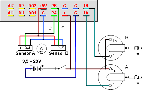
Schéma zapojení
Základní schéma zapojení je uvedeno pro variantu se dvěmi indukčními cívkami. V případě varianty s jednou indukční cívkou odpadá snímač a cívka s označením B.
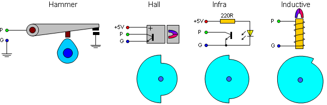
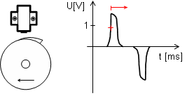
Snímač otáčení
Významným prvkem v soustavě elektronického zapalování je snímač otáčení. Lze použít jakýkoliv typ snímače, který splňuje podmínku vzestupné hrany (změny napětí) 0 -> 1,5V. Tento požadavek splňují indukční a Hallovy snímače otáčení. Při amatérské instalaci lze použít i optický nebo mechanický (kladívkový) snímač. Pro dosažení maximální spolehlivosti je ovšem vhodné zvolit továrně vyráběný snímač otáčení. Signálový vodič ze snímače otáčení je vhodné vést mimo rušení nebo použít vodiče ve stíněném provedení, pro eliminování případných rušivých vlivů elektroinstalace.
Na základě každého platného impulsu ze snímače otáčení je prostřednictvím soustavy zapalování a indukční cívky generována jiskra.
Nastavení předstihu

Posledním a nejdůležitějším bodem instalace je správné nastavení zapalování tak, aby mohlo bezchybně plnit veškeré požadované funkce.
V první fázi je důležité si uvědomit jaký maximální předstih zážehu motor vyžaduje. Tento maximální předstih je nutné nastavit na snímači otáčení (např. 35°) a zároveň jej zadat jako referenční hodnotu do aplikace Ignition Control v záložce Křivka předstihu do položky Snímač otáčení. Vždy je tedy nutné, aby se hodnota předstihu nastaveném na snímači otáčení shodovala s předstihem zadaným v programu. Od tohoto údaje se odvíjí přepočet křivky předstihu do tabulky a zejména přesnost Online vizualizace aktuálního předstihu. Hodnotu předstihu na snímači otáčení je možné dodatečně opravit porovnáním skutečné hodnoty předstihu zjištěné např. stroboskopem a hodnoty předstihu udávané v Online vizualizaci.
Na motocyklových motorech se udávají předstihy zážehu pro snazší nastavení v [mm], proto program umožňuje automatický přepočet předstihu z [mm] na [°]. Okno přepočtu předstihu se aktivuje dvojklikem myši v záložce Křivka předstihu a položce Snímač otáčení.
Program Ignition Control
Elektronické zapalování obsahuje řadu funkcí jejichž nastavení lze s výhodou provést prostřednictvím osobního počítače programem Ignition Control. Komunikace s počítačem probíhá prostřednictvím komunikační sběrnice USB. Aplikace pracuje pod operačním systémem Windows 95 a vyšší. Instalace vyžaduje 4MB volného prostoru na pevném disku počítače. Minimální konfigurace osobního počítače je Pentium 166MHz s 32MB RAM.
Program Ignition Control je rozdělen do čtyř samostatných částí:
- Online vizualizace
- Křivka předstihu
- Rozšířené funkce
- Kalibrace čidel
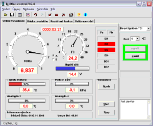
Online vizualizace zobrazuje tyto základní parametry:
- Otáčky motoru
- Předstih zážehu
- Napětí sítě (Palubní napětí)
- Digitální vstupy (Pa, Pb, DI1, DI2, DI3, DI4)
- Digitální výstupy (DO1, DO2)
- Analogové vstupy (AI1, AI2, AI3, AI4)
Ke spuštění Online vizualizace je vždy nutné propojení počítače a zapalování USB kabelem s následným spuštěním vizualizace tlačítkem Start. V případě, že se po stisku tlačítka Start nezobrazí aktuální data pak zkontrolujte správnost připojení komunikačního kabelu, případně číslo použitého komunikačního portu a správnost napájení zapalování.
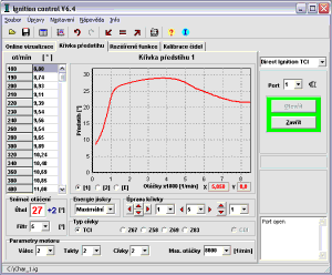
Křivka předstihu
Základní vlastností zapalování je řízení předstihu v závislosti na aktuálních otáčkách motoru. K nastavení charakteristiky řízení předstihu slouží záložka Křivka předstihu.
Buzení cívek
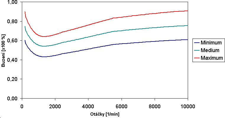
Pro optimalizaci typu indukční cívky a jejího buzení slouží položka Energie jiskry. Pro indukční cívky s odporem menším než 4 ohmy (min 2,5 ohmů) je nutné nastavit buzení střední až minimální, které zamezí přebuzení indukční cívky a jejímu přehřívání. Pro cívky s odporem větším než 4 ohmy slouží nastavení buzení střední a maximální. Kompromisem buzení indukční cívky je nastavení pro řízení energie jiskry, které řídí buzení na základě hodnoty palubního napětí.
| Palubní napětí / otáčky | Řízené buzení |
| > 9V | Maximální |
| 9V - 11,5V | Střední |
| < 11,5V / < 3300ot/min | Minimální |
| < 11,5V / 3300 až 6500ot/min | Střední |
| < 11,5V / > 6500ot/min | Maximální |
Předdefinované průběhy buzení cívek
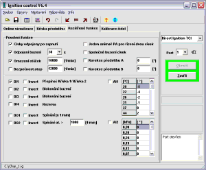
Rozšířené funkce
Zejména pro zvýšení bezpečnosti provozu a také pro vyšší možnosti při nastavení křivky předstihu zapalování slouží rozšířené funkce. Rozšířené funkce tvoří soubor digitálních vstupů DI1 až DI4, výstupů DO1, DO2 a analogových vstupů AI1 až AI4. Funkce jednotlivých rozšiřujících vstupů a výstupů lze libovolně povolovat a případně také invertovat.
- Odpojení buzení 5 až 120s
Povolení automatického vypnutí buzení indukčních cívek po uplynutí nastavené doby 5 až 120s. Toto opatření zamezuje zničení indukčních cívek trvalým budícím proudem.
- Omezení otáček 1000 až 25000ot/min
Povolení funkce omezení otáček způsobí pravidelné přerušování buzení indukční cívky, po překročení zvolené meze otáček.
- Bezpečnostní stop 1000 až 28000ot/min
Překročení nastavených otáček způsobí úplné přerušení buzení. Činnost buzení je opět obnovena po zastavení motoru.
- DI1 - Přepínání Křivka 1 / Křivka 2
Umožňuje snadné přepínání křivek předstihu kdykoli za běhu motoru. Není-li funkce aktivována je pro řízení vždy použita Křivka 1.
- DI2 - Blokování Buzení
Poskytuje okamžitou možnost blokování rozběhu nebo běhu motoru.
- DI3 - Blokování Buzení
Poskytuje okamžitou možnost blokování rozběhu nebo běhu motoru.
- DI4 - Rezerva
Vstup rezervovaný pro budoucí použití.
- DO1 - Spínaní [x1/min]
Výstup na otáčkoměr
- DO2 - Spínaní [1/min]> Zadané otáčky
Výstup spínaný na základě počtu zadaných otáček
- AI1, AI2 - Korekce předstihu
Základní křivka předstihu je tvořena závislostí na otáčkách (viz. záložka Křivka předstihu) . Tuto křivku je možné korigovat signálem z analogových vstupů AI1 a AI2. Analogová čidla připojená k těmto vstupům je nejprve nutné zkalibrovat (viz. záložka Kalibrace čidel). Zkalibrovaná hodnota čidla se projeví v záložce Rozšířené funkce, kde je možné zadat pro danou skutečnou hodnotu z čidla odpovídající korekci předstihu v rozsahu <-15°;+15°> . Pro povolení korekce je nutné povolení funkce potvrzením políčka AI1 nebo AI2.
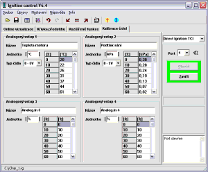
Příklad kalibrace čidla v záložce Kalibrace čidel. Kde se jedná o teplotní čidlo, které dává signál v rozsahu 0-5V.
0,0V (0%) = 20°C
0,5V (10%) = 22°C
1,0V (20%) = 26°C
1,5V (30%) = 31°C
2,0V (40%) = 37°C
2,5V (50%) = 44°C
Příklad korekce předstihu v záložce Rozšířené funkce. Předstih je korigován od teploty motoru, kde např. při teplotě 22°C je předstih zmenšen o 4°.
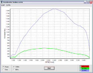
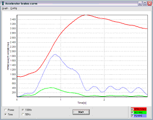
Akcelerační brzda
Mezi nové funkce Online vizualizace patří Akcelerační brzda, která provádí rychlý 5s záznam otáček motoru s následným výpočtem derivace (zrychlení) otáček, která úměrně odpovídá kroutícímu momentu motoru.
Průběh měření
- Před použitím je vhodné zkontrolovat zadání Omezení otáček motoru
- Necháme motor běžet na volnoběžné otáčky a připravíme se na jeho zrychlení
- Stiskneme tlačítko start
- Odměření doby 1s do spuštění záznamu
- Probíhá samotný záznam po dobu 5s
- Ukončení záznamu a vyčtení naměřených hodnot otáček ze zapalování
- Zobrazení a přepočet naměřených hodnot do grafu
Proč použít bezkontaktní elektronické zapalování Ignition
Elektronické zapalování umožňuje velmi přesné řízení předstihu, což má za následek výrazné zlepšení chodu motoru v nízkých a zejména pak ve vysokých otáčkách. Dochází ke zlepšení startování (optimální předstih), zvýšení výkonu motoru (vysoká energie jiskry) a při dodržení pravidel úsporné jízdy dojde i ke snížení spotřeby. Zapalování je možné použít bez úprav pro 6V i 12V el. (zaručeně pracuje při napětích od 3,5V do 25V).