 CZ
CZ
Universal Ignition TCI
No longer for sale!
There is a replacement – MASTER MINI ignition.
The ignition is developed for two or four-cycle automobile and motorcycle engines. The ignition allows excitation of one or two induction coils with programmable advance curve and coil excitation intensity control.

Technical Specification
Main features of Universal:
- The induction ignition type - TCI
- 1x pick up input, 2x outputs TCI, 1x signal input
- Support pick up sensors HALL, OPTO
- Advance control based on the principle of time delay
- Temperature sensing or excitation block
- Limited support TCI coils, resistance> 2.5 Ω
- 2D maps of advance
- RS232 communication
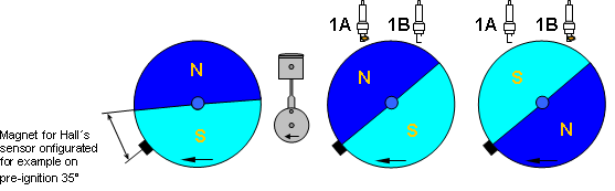
Rotation sensor is placed externally, outside of the housing ignition (+5 V, P, Z). It is advantageous to use the Hall effect, an optical sensor or may be used even induction sensors, but with the possibility of excitation of only one coil or two coils simultaneously. Excitation coils are distributed on the basis of the single rotation sensor (change in H-> L or L-> H). All the functions and optional working ignition regimes can be set by a personal computer. For this purpose there is a Ignition Control application which also enables online visual control of real values of turns, advance (set-up time). To connect the personal computer and the ignition is used standard extension cable RS232, serial line.
Advance control is realized by ignition microprocessor that sets the delay time of ignition (the ignition advance) according to the set curve and actual turns.
Using the extension function input Ex it possible change over the ignition curves. Input Ex is internally connected to signals DI1 (choise of curves), DI2 (excitation block) and AI1 (change of advance at the base of temperature or under-pressure). The pre-ignition directing is realized by the conversion of demanded pre-ignition curve into schedule of time delays. Depending on actual turns of a motor the individual time delays are chosen from the schedule and via the microprocessor exactly measured and that is the way to efficiently control the advance.
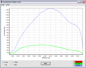
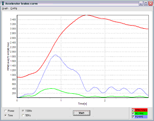
The application Ignition Control also provides the function of pre-ignition debugging by acceleration brake where the acceleration of motor is watched when repressing its own mass. The assumption is that the acceleration of the engine speed is adequate to motor torque. This way you can determine the relative power and torque of the engine or its changes.
Main features
- The induction ignition type - TCI
- Supplay voltage range 3,5 to 25V
- Engine working speed 0 to 25.000 rpm
- Working temperature range -40 to 85°C
- Used solid connectors FASTON
- Protection cover IP54
- Communication by COM port (RS232)
- Two selectable advance curve
- Selectable curve of excitation induction coils
- Extended function EX (DI1, DI2, AI1, AI2)
- Change curves during engine work
- Monitoring actual state of engine
- Engine work - time record
- Acceleration brake
Basic technical parameters
| Parameters | Range |
| Supply voltage | 3,5 to 25V, (overvoltage protection 33V) |
| Engine working speed | 0 to 25.000 RPM |
| Advance control | 0 to 90° |
| Working temperature | -40 to 85°C |
| Engine speed for advance control | 180 to 20.500 RPM |
| Flash energy control | Table, Max., Med., Min., Direction |
| Coil current | max. 15A/0,085Ω (MOSSFET) |
| Inductor resistance | > 2.5 ohm |
| Supply voltage for rotating sensor | +5V/100mA |
| Digital input (Ex = DI1, DI2, AI1, AI2) | DI (0 to 1V = L, 3 to 20V = H), AI (0 to 5V) |
| Auto. disconnection inductors | 5 to 120s after stop of engine |
| Package size | 120x68x28 mm |
Connector scheme
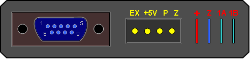
Wiring and significations
| Signification | Meaning | Range, active level |
| + | Supply | 3.5 to 25V, (over voltage protection 33V) |
| G | Ground | 0V |
| 1A | Inductor coil power switch A | Max. 15A /0.085Ω (MOSFET) |
| 1B | Inductor coil power switch B | Max. 15A / 0.085Ω (MOSFET) |
| +5V | Sensors supply output +5V | +5V, 100mA |
| P | Rotating sensor | -60 až 60V, rise edge 0 -> 1.2V |
| Ex | Extended input | DI (0 to 1V=L, 3 to 20V=H), AI (0 to 5V) |
Installation scheme
Main scheme in variant with two coils.
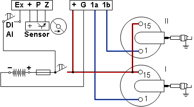
Conection scheme of rotation engine sensors
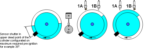
The advance set up
First and the most important point in the installation are the proper settings of the ignition to serve all demanded functions perfectly.
First it is necessary to know what maximal pre-ignition advance each engine demands in the first period. This maximal pre-ignition advance must be set in the reading sensor of rotation (e.g. 35°) and also be held as a reference value in the program in a Pre-ignition curve bookmark, item Rotation Reading Sensor. Always the value of pre-ignition set in the sensor must be adequate to the value set in the program. According to this value the conversion of the ignition advance curve is saved in a schedule, mainly the actual truth of On-line visualisation. The value of advance on the rotation reading sensor can be corrected later by comparing the actual value of ignition found out e.g. by a stroboscope to the value of advance set in On-line visualisation.
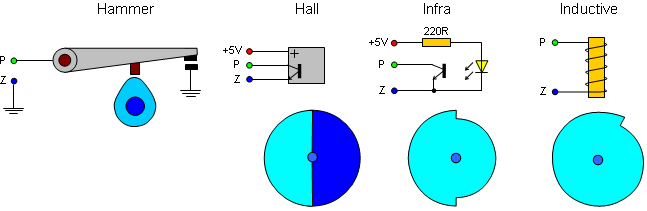
Optical sensor
Hall sensor
The pre-ignition directing is realized by the ignition microprocessor that sets the delay time of ignition (the ignition advance) according to the set curve and actual turns.
For easier set up the ignition advance is determined in [mm] in motorbike engines. That is why this program enables the automatic ignition conversion from [mm] to [°]. The ignition conversion window is activated by double click of the mouse in bookmarks Ignition curve and items Rotation reading sensor.
Signal indicator
The profile of all functions is saved in the ignition memory that keeps data even without power supply. The memory content is recorded from the Ignition Control program.
If the memory has never been recorded or the interruption of the last recording happened this state will be signalized by a short red flashing after switch-on. All set ups will then be given by a producer. The right memory content is indicated by a constant green light. The recording data from the computer is indicated by a red constant light. If the ignition changes into the protective mode (the engine is not running and the regime is allowed) the green indicator stops lightning (the inductors are not being excited). After getting the impulse from the rotation reading sensor the green indicator will switch on again (re-excitation).
Ignition Control application
The electronic ignition consists of many functions and their set-up can be realized through a personal computer with Ignition Control program. The computer communicates through the RS232 interface of speed 19200Bd. That is why the computer must have at least one COM port and/or USB/RS232 transducer. The application works under the Windows 95 or higher. It requires 4MB of empty space in hard disc. The minimum PC configuration is Pentium 166MHz, 32MB RAM is accurate.
Ignition Control Program is divided into four individual parts:
- Online visualisation
- Ignition advance curve
- Extended functions
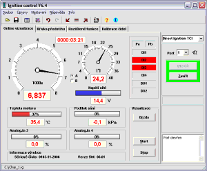
Online visualisation showing this parameters
- Engine RPM and Advance
- Ignition advance
To run visualization it is always necessary to connect the computer with the ignition by a serial extended cable, to open the communication port and to run the visualization by pressing the button Start. In case that after pressing the button Start the real data do not display please control the connection of communication cable, the number of the used communication port and the voltage of the ignition.
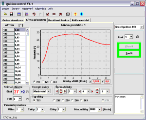
Ignition advance curve
The basic character of the ignition is the directing the ignition advance according to real turns of the engine. To set ignition advance directing characteristics there is Ignition advance curve bookmark.
Flash energy
To optimize the type of the inductors and its excitation there is Flash energy button. It is necessary to set medium or minimum excitation that will protect the inductors against the over excitation and their over heating when using inductors with resistance lower than 4ohm (min 2,5 ohm). If using the inductors with the resistance higher than 4ohm there is medium or maximal excitation settings. The settings of Flash energy directing that directs exciting according to values of board voltage is the compromise of the excitation inductors.
| Board voltage | Control flash energy |
| > 9V | Maximum |
| 9V - 11,5V | Medium |
| < 11,5V / < 3300RPM | Minimum |
| < 11,5V / 3300 - 6500RPM | Medium |
| < 11,5V / > 6500RPM | Maximum |
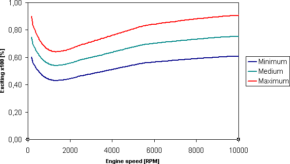
Průběh buzení je možné zadat vlastní modelováním křivky tahem myší nebo zadat tabulkou. Je možné volit buzení v rozsahu 20 až 95% z doby otáčení. Lze tak snadno kompenzovat zásadní nevýhodu indukčních zapalování a to pokles proudu s růstem otáček. Vhodný průběh přidává buzení pro start a pak prudce klesne na volnoběžné buzení a pak opět roste při zvyšování otáček viz. graf Předdefinované průběhy buzení cívek.
It is possible to configurate coil excitation course by your own curve modeling using mouse pulling or write in table. You can set excitation from 20 to 95% per a round. It is easy compensatation for major disadvantage of inductive ignition and that is a drop in current with an increase in speed. Suitable process adds excitation to start and then drops to idle excitation and then increases again to increase speed, see Predefined graph of coil excitations.
Pre-defined process of coil exciting
Acceleration brake
There is a new function in Online visualization. It is Acceleration brake that realizes fast 5 second engine record with the calculation of the turn derivation (acceleration). It proportionately responds to torsional moment.
Measure process
- Check the Engine Turn Limits settings before use
- Leave the engine run idlely and get ready for its acceleration
- Press Start button
- Wait exactly 1 second to run the record
- Running of the record for 5 seconds
- End up the record and read the measured values of turns from ignition
- Display and conversion the measured values to the graph
Why you should use the Universal Ignition
The electronics ignition allows very exactly direction of advance. This provide more of engine power in wide rande RPM. The ignition allows very easy engine start (optimal advance), more power (high energy of flash) and with the rules of economy driving then decrease of fuel consume. The ignition guaranteed works in voltage range from 3,5V to 25V.